Showing posts with label Auto CAD. Show all posts

Tuesday, May 3, 2011

Auto CAD - Draw Command - Drawing Ellipse

 DRAWING ELLIPSE

There are three ways to initiate the Ellipse Command. They are:


An Ellipse is one object. There are three methods of creating Ellipse In AutoCAD.:
i.    Specify one axis and the end of the second
ii.    Specify the center and the ends of each axis
iii.    Create an ellipse arc


The Ellipse command options are :

a.   Axis End

This default option requires Picking three points as indicated in the command sequence above.


b.   Rotation

If the rotation option is used with the Axis End method, the following syntax is used:

        <Other axis distance>/Rotation : R
        Rotation around major axis : Pick or (value)


The specified angle is the number of degrees the shape is rotated from the circular position.

c.   Center

With many practical application, the center point of the ellipse is known, and therefore the center option should be used.

    Command  : ellipse
    Arc/Center/<Axis endpoint1> : C
    Center of ellipse : Pick or (coordinates)
    Axis endpoint : Pick or (coordinates)
    <Other axis distance>/Rotation : Pick or (coordinates)
( This distance is measured perpendicularly from the established axis )

The Rotation option  appear and can be invoked after specifying the Center first Axis endpoint.


d.   Arc
   
Use this option to construct an elliptical arc ( partial ellipse ). The procedure is identical to the Center option with the addition of specifying the start and endpoint for the arc.

        Command : ellipse
        Arc/Center/<Axis endpoint 1>: a
        <Axis endpoint 1>/center : pick or (coordinates)
        Axis endpoint 2 : pick or (coordinates)
        <Other axis distance>/Rotation : pick  or (coordinates)
        Parameter/<start angle>: Pick or (angular value)
        Parameter/Included/<end angle> : Pick or (angular value)


The ELLIPSE command approximates an ellipse by drawing a polyline composed of short arc segments.

a.   Ellipse by axis and eccentricity

One method of drawing an ellipse is to choose the default options :

Example ;

< Axis endpoint 1 > / Center  :        P1
Axis endpoint 2 :                      P2
< Other axis distance > / Rotation  :  P3


b.   Ellipse by axis and rotation

Example ;

< Axis endpoint 1 > / Center  :
Axis endpoint 2 :                                         P1
R                                                                P2
Rotation around major axis :                        For rotation

The rotation can be from 0 to 89.4 degrees.


c.   Ellipse by center and two axes

Example ;

C                                                                 For center
Center of ellipse :                                         P1
Axis endpoint :                                             P2
Other axis distance :                                     P3


d.   Ellipse by center, one axis and rotation
Example ;

C                                                                For center
Center of ellipse :                                        P1
Axis endpoint :                                            P2
R
Rotation around major axis :                        For rotation

The rotation can be from 0 to 89.4 degrees.


To Be Continue.. Next > MODIFY OBJECTS.


Learn Basic Auto CAD

Auto CAD - Draw Command - Drawing Circle

DRAWING ARC

An arc is defined as a curved line that describes a portion of the circumference of a circle.  There are 3 ways to initiate the Arc Command (Picture below) . They are:


You can create Arc objects using several methods. These methods are embedded within the Arc Command itself in the form of Command Option, which are listed in the sub-menu when you select Draw | Arc on the menu bar. The Arc command options are :

1.   3 Points

With this method, three points define the  Start point of the arc, a Second point that the arc passes through, and the arc’s Endpoint.
                   
Example ( Picture A ) ;
 
 Command: _arc Specify start point of arc or [Center] : pick 1          1
 Specify second point of arc or [Center/End] : pick 2                         2
 Specify end point of arc : pick 3                                                       3

You may use the keyboard and specify the coordinates, or you may  use
the mouse to defining any of these 3 points.


2.   Start Point, Center, End Point ( S, C, E )

Center refers to the Center point of the circle of which the arc is a part.
                   
Example( Picture B )  ;
 
 Command: _arc Specify start point of arc or [Center] :  pick 1   ( start )
 Specify second point of arc or
   [Center/End]: _c Specify center point of arc: pick 2                 ( center )
 Specify end point of arc or [Angle/chord Length] : A                  ( end )
 Specify included angle : 90


3.   Start Point, Center, Included Angle  ( S, C, A )

Requires specifying the Start point and the Center of the arc first, and then specifying the Included Angle.
                   
Example( Picture C )  ;
 
Command: _arc Specify start point of arc or [Center] : pick 1      ( start )
Specify second point of arc or
  [Center/End]: _c Specify center point of arc : pick 1                  ( center )
Specify end point of arc or
  [Angle/chord Length]: _a Specify included angle : 270                ( angle )


4.   Start Point, Center, Length Of Chord  ( S, C, L )

Requires specifying the Start point and the Center of the arc first, and then specifying the Length of chord.
                   
    Example ( Picture D);

  Command: _arc Specify start point of arc or [Center]  : pick 1     A
  Specify second point of arc or
    [Center/End]: _c Specify center point of arc : pick 2                  B
  Specify end point of arc or
    [Angle/chord Length]: _l Specify length of chord:  2.5


5.   Start Point, End Point, Radius  ( S, E, R )

Allows specifying both the Start and the End point of the arc. The arc will automatically be calculated when you specify the included radius.
                   
Example(Picture E);

  Command: _arc Specify start point of arc or [Center] : pick 1  A
  Specify second point of arc or [Center/End]:  e
  Specify end point of arc : pick 2                                               B
   Specify center point of arc or
     [Angle/Direction/Radius]: _r Specify radius of arc:  1


6.   Start Point, End Point, Included Angle  ( S, E, A )

Requires specifying the Start point and the End point of the arc first, and then specifying the included angle.

Example(Picture F) ;

 Command: _arc Specify start point of arc or [Center] : pick 1      A
 Specify second point of arc or [Center/End]:  e
 Specify end point of arc : pick 2                                                  B
 Specify center point of arc or
   [Angle/Length of Chord/<Endpoint>]: Angle Included angle:  90


7.   Start Point, End Point, Starting Direction  ( S, E, D )

The direction is tangent to the start point. (Picture below)


8.   Center, Start Point, End Point ( C, S, E )

The options include start, center, end but the are not in the same order.
(Picture below)


9.   Center, Start Point, Included Angle ( C, S, A )

The options include start, center, angle.  However, they are not in the same order. (Picture below)


10.   Center, Start Point, Length Of Chord  ( C, S, L )

This is similar to the start, center and length option but  not in the same order. Length means length of chord. (Picture below)


To Be Continue.. Next > Drawing Ellipse.

Auto CAD - Draw Command - Drawing Circle

DRAWING CIRCLE
The CIRCLE command has many options, which include center, radius, center, diameter; two points; three points; tangent, tangent, radius; tangent, tangent, tangent.

There are three ways of initiating the Circle Command (Picture below).
They are :


You can create Circle objects using several methods. These methods are embedded within the Circle Command itself in the form of Command Options. These command options are listed in the sub-menu when you select Draw | Circle on the menu bar.

The Circle command options are :

1.   Center and Radius

This is the classical method. The first point defines the  center of the circle, the second one the radius.

Example ( Picture A) ;
 
Command  :   _circle Specify center point for circle or
                     [3P/2P/Ttr (tan tan radius) pick                        
Specify Diameter radius of circle or [Radius] :  r
Specify radius of circle Radius / <Diameter> : 20                                               

Specifying the Center Point of the circle :
 i.   By using the mouse to point to the location and clicking
      the left mouse button
 ii.  By using the command Line and entering the coordinates
      of the point in the x, y format
 
Specifying the Radius of the circle :
i.    By using the mouse to point and left click at the location of
      the edge of the circle
ii.   Enter the coordinates of the edge of the circle at the
      Command Line prompt.
iii.  Enter the radius length and angle value in the @ length
     < angle format at the Command Line prompt. This method is
     superfluous because the length (value) of the radius is constant
     through all angle values.
iv.  Enter the value of the radius at the Command Line prompt.

If you want to use the previous radius value, you just press the Enter key, or else, you would have to specify the new radius

2.   Center and Diameter
After the center for the circle has been defined, the diameter can be given.

Example( Picture B )  ;
 
            Command  :   _circle Specify center point for circle or
                                 [3P/2P/Ttr(tan tan radius) pick                       
            Specify radius of circle or [Diameter]  :  d
            Specify diameter of circle Diameter / <Radius>  :  40      

When you specify the diameter of the circle, it would draw a circle with radius half the length of the diameter.


3.   2 Points ( 2P )

With this option, the user can specify two points constituting the endpoints for the diameter of the circle.
                   
Example ( Picture C ) ;
 
             Command   :  CIRCLE Specify center point for circle or
                                    [3P/2P/Ttr (tan tan radius)] :                     2P                  
             Specify first end point of circle's diameter  :   pick 1         P1
             Specify second end point of circle's diameter  :   pick 2    P2


4.   3 Points ( 3P )

This option allows the user to define the circle by specifying three points on its circumference.
                   
Example ( Picture D )  ;
 
             Command   :  CIRCLE Specify center point for circle or
                                   [3P/2P/Ttr (tan tan radius)] :                     3P                  
             Specify first end point of circle's diameter  :   pick 1         P1
             Specify second end point of circle's diameter  :   pick 2    P2
             Specify third end point of circle's diameter  :   pick 2        P3


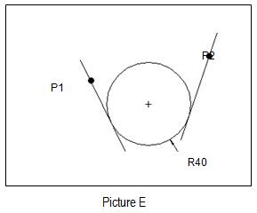
5.   Tangent, Tangent And Radius ( TTR )

This allows the user to define two tangential points, and then the radius of the circle.

        Tangent-Tangent-Radius Mode - Method 1
        This mode is very powerful when constructing a circle tangent to
        two entities. Illustrated below is an application on the use of the
        TTR mode to construct a circle tangent to two line segments.
        Study the prompt below to create this type of circle.

         Example (Picture E) ;

             Command:  CIRCLE Specify center point for circle or
                                [3P/2P/Ttr (tan tan radius)] :                            TTR
             Specify point on object for first tangent of circle : pick 1        P1
             Specify point on object for second tangent of circle : pick 2   P2
             Specify radius of circle  : 40


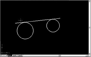
        Tangent-Tangent-Radius Mode : Method 2
        Illustrated below is an application of using the Circle TTR mode
        to construct a circle tangent to the line segment on another circle.
        Study the prompt below to create this type of circle.

        Example ( Picture F ) ;

            Command:  CIRCLE Specify center point for circle or
                               [3P/2P/Ttr (tan tan radius)] :                             TTR
            Specify point on object for first tangent of circle : pick 1        P1
            Specify point on object for second tangent of circle : pick 2   P2
            Specify radius of circle  : 40


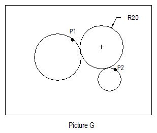
        Tangent-Tangent-Radius Mode : Method 3
        Illustrated below is an application on the use of Circle TTR mode
        to construct a circle tangent to another two circles. Study the
        prompt below to create these this types of circles.

        Example ( Picture G ) ;

            Command:  CIRCLE Specify center point for circle or
                               [3P/2P/Ttr (tan tan radius)] :                            TTR
            Specify point on object for first tangent of circle : pick 1       P1
            Specify point on object for second tangent of circle : pick 2  P2
            Specify radius of circle  : 20


To Be Continue.. Next > Drawing Arc.

Monday, May 2, 2011

Auto CAD - Draw Command - Drawing Line

DRAW COMMAND

Draw commands create objects. An object is the smallest component of a drawing. The draw commands listed immediately below create simple objects and are discussed in this unit. Simple objects appear as one entity.

Line, Circle, Arc, Ellipse, Pline, Polygon, Donut

Normally, there are three methods that can be used to access draw commands. We can use either the draw toolbar, command window or pull-down menu (Picture below).


DRAWING LINE
This is the fundamental drawing command. Use the line command to construct a line from one endpoint to the other. One or several line segments can be drawn with the line command. You can specify the endpoints of lines using two-dimensional or three-dimensional coordinates.

The LINE command can be initiated using any of the following methods (Picture below) :


When you initiate the Line command, AutoCAD requests you to specify a From point (starting point) and To Point (ending point). These requests are displayed in the Command Window. Most Command requires a few steps to complete. The Command Window tells you which step you are currently at. The Command Window also displays the option available to you for each of the command that you initiate. 

There are 2 ways of specifying the From Point :

1.    By using the mouse to point to the location and clicking the left mouse button.
2.    By using the Command Line and entering the coordinates of the point  (coordinates x, coordinates y).

There are 3 ways of specifying a To Point :

1.    By using the mouse to point to the location and clicking the left mouse button.
2.    By using the Command Line and entering the coordinates of the point (coordinates x,  coordinates y).
3.    By using the Command Line and entering the length of the line, and the angle of the  line in relation to the From Point ( @ length < angle ).

There are several methods to draw lines. They are :

1)     Absolute coordinates


2)     Relative coordinates


3)     Relative polar coordinates


Option of the LINE command

1.     CLOSE

The  CLOSE   option  ( key-board  :   c )   closes   a  polygon  ( minimum of three sides ) when all segments are drawn in the same command sequence. Picture below.


2.    UNDO

The UNDO option ( key-board  :  u  ) allows the user to undo the last segment drawn without ending the command procedure. Refer picture below.

Example ;

    Command  :     LINE From point : 50,50          P1
    To point     :     @50<0                                     P2
    To point     :     @50<0                                     P3’
    To point     :     u  ( key-board = u )              back to P2
    To point     :     @50<90                                   P3
    To point     :     @50 <180                                P4
    To point     :     @50<270  ( or   close )         P1 = P5


To Be Continue.. Next > Drawing Circle.

Auto CAD - Save a Drawing

After you finish a drawing, you will have to save the  drawing files for later use. You can save the drawing at anytime using any of the save command. AutoCAD  provides automatic saving, backup files, and other options for saving.

To save a drawing from the file menu ;

Step 1 - From the File menu, choose save.


Step 2 - In the Save Drawing As dialog box under File Name, enter the new drawing name; the file extension is not required. Then choose Save. Picture below shows the Save Drawing As dialog box.

If you have previously have saved and named the drawing, AutoCAD saves any sequent changes and redisplays the command prompt. If you have never saved the drawing, the Save Drawing As dialog box is displayed.


To save a drawing automatically ;

Step 1 - From the Tools Menu, choose options.


Step 2 - After that choose OK.

In the Options dialog box, Open and Save tab, select Automatic Save and enter a number  in Minutes Between Saves. (Refer to Picture below).


Sunday, May 1, 2011

AUTOCAD INTERFACE

As with all other Windows based softwares, you use AutoCAD through its Graphical User Interface or GUI. This user interface is shown in Picture left. It is simply known as the AutoCAD Interface.

This interface is the screen that greets you when you first start AutoCAD. It comprises the Menu Bar at the top, the Status Bar at the bottom, the Command Window, the Graphics Window and Four Toolbars.


THE MENU BAR
Located at the top of the AutoCAD Interface, the Menu Bar provides navigational access to all AutoCAD commands and features. Most of these commands are also featured as buttons on the various Toolbars. Picture below shows the Menu Bar.


THE STATUS BAR
Located at the bottom of the AutoCAD Interface is the Status Bar. It indicates the pointing device’s current co-ordinates and the various Drawing Aids. Picture below shows the AutoCAD Status Bar.


THE COMMAND WINDOWS
Located above the Status Bar is the AutoCAD Command Windows. This window displays the history of the commands that were used during the drawing session. It also contains a Command Line that allows you to type in the AutoCAD command directly during your drawing session. Picture below shows the AutoCAD Command Window.


 This window is user sizeable. It allows you to view more, or less than two (default) lines of command history. The command window is by default located at the bottom of the AutoCAD Interface above the Status bar. It can be detached from its default location to become a floating window, or be docked to the top of the Interface.

THE GRAPHICS WINDOW
The Graphics window is the area of the interface where your drawing is shown. There are two scrollbars, one on the right side (vertical) and the other, at the bottom  (horizontal) of this window.

The vertical scrollbar allows you to scroll the diagram vertically, while the horizontal scrollbar allows you to pan the diagram horizontally. Picture right shows the graphic window with a sample drawing and the two scroll bars mentioned above.


However, for the sake of providing a better contrast between a drawing and the window’s background, subsequent figures showing the Graphics Window from this unit onwards shall show the background in white and drawing in black.

TOOLBARS
Picture below shows the four toolbars, which by default the AutoCAD Interface opens with. There are:


DRAWING AIDS
One of the most overpowering features of AutoCAD over manual drafting instrument is its collection of Drawing Aids. These are:

Unit and Precision of Measurement
AutoCAD allows you to select the units of measurement in the precision level with which you want to produce your drawings. These are selected using the Unit Control dialog box, which can be launched from the Format menu on the Menu Bar.

Grid
The Grid is a drawing aid that serves a purpose, which is identical to that of a sheet of grid paper (often called graph paper). Drawing with the Grid is similar to drawing on a sheet of grid paper. It helps you to align objects and to visualize the distances between them.

By default, the Grid appears as equally spaced dots over an area that is specified by the limits of the drawing. You may turn the Grid On or Off at any time during your drawing session.

The distance between the dots is called the Grid Spacing. You can set the horizontal and the vertical grid spacing to identical or different values. The Grid Spacing is set using the Drawing Aids dialog box, which can be launched from the Tool menu on the Menu bar. Picture below shows the Grid.


Snap
Snap is a feature that restricts the movement of the cursor to discrete intervals that you have defined. When Snap is switched On, the cursor seems to adhere onto invisible fixed points, as you move it over the drawing area. Snap is useful when you want to draw certain objects using precisely spaced drawing intervals. Like grid, Snap is also set in the Status Bar. It too, can be switched: On, or  Off  at any time during the drawing session.

Orthogonal

Orthogonal  to AutoCAD is what the parallel rule and the set squares to the drafting board. It is an invisible but indispensable aid that helps you to draw lines that are parallel, or at right angles, to one another precisely. When Orthogonal is On, you are restricted to only vertical and horizontal movements of the cursor; no diagonal movement can be made. To draw diagonally, you have to switch off the Orthogonal drawing aid.

Object Snap

Object Snap is a set of drawing aids you would find very difficult to emulate manually. Even if you could, it would mean performing a series of measuring and calculating tasks. The Object Snap aids of AutoCAD allow you to accurately locate the following target points, with just a click of the mouse:

These aids drastically reduce the time you would need to complete a drawing drastically. Furthermore, since the target point is computed and located by AutoCAD automatically, precision is maintained throughout the drawing session.

Sunday, April 10, 2011

CADD - INTRODUCTION

INTRODUCTION

CADD is an acronym for Computer-Aided Design Drawing or Computer-Aided Drafting Drawing. CADD allows you to accomplish design and draf activities using a computer. A CADD software package, such as AutoCAD, enables you to create designs and generate drawings to documents designed.

Design is a broad field involving the process of making an idea into a real product or system. The design process requires repeated refinement of an idea or ideas until a solution results-a manufactured product or constructed system.

Traditionally, design involves the use of sketches, drawings, renderings, 2-dimensional and 3-dimensional models, prototypes, testing, analysis and documentation. Drafting is generally known as the production of drawings that are used to document a design for manufacturing or construction or to archive the design.