Showing posts with label Drawing. Show all posts

Tuesday, May 3, 2011

Auto CAD - Draw Command - Drawing Circle

DRAWING CIRCLE
The CIRCLE command has many options, which include center, radius, center, diameter; two points; three points; tangent, tangent, radius; tangent, tangent, tangent.

There are three ways of initiating the Circle Command (Picture below).
They are :


You can create Circle objects using several methods. These methods are embedded within the Circle Command itself in the form of Command Options. These command options are listed in the sub-menu when you select Draw | Circle on the menu bar.

The Circle command options are :

1.   Center and Radius

This is the classical method. The first point defines the  center of the circle, the second one the radius.

Example ( Picture A) ;
 
Command  :   _circle Specify center point for circle or
                     [3P/2P/Ttr (tan tan radius) pick                        
Specify Diameter radius of circle or [Radius] :  r
Specify radius of circle Radius / <Diameter> : 20                                               

Specifying the Center Point of the circle :
 i.   By using the mouse to point to the location and clicking
      the left mouse button
 ii.  By using the command Line and entering the coordinates
      of the point in the x, y format
 
Specifying the Radius of the circle :
i.    By using the mouse to point and left click at the location of
      the edge of the circle
ii.   Enter the coordinates of the edge of the circle at the
      Command Line prompt.
iii.  Enter the radius length and angle value in the @ length
     < angle format at the Command Line prompt. This method is
     superfluous because the length (value) of the radius is constant
     through all angle values.
iv.  Enter the value of the radius at the Command Line prompt.

If you want to use the previous radius value, you just press the Enter key, or else, you would have to specify the new radius

2.   Center and Diameter
After the center for the circle has been defined, the diameter can be given.

Example( Picture B )  ;
 
            Command  :   _circle Specify center point for circle or
                                 [3P/2P/Ttr(tan tan radius) pick                       
            Specify radius of circle or [Diameter]  :  d
            Specify diameter of circle Diameter / <Radius>  :  40      

When you specify the diameter of the circle, it would draw a circle with radius half the length of the diameter.


3.   2 Points ( 2P )

With this option, the user can specify two points constituting the endpoints for the diameter of the circle.
                   
Example ( Picture C ) ;
 
             Command   :  CIRCLE Specify center point for circle or
                                    [3P/2P/Ttr (tan tan radius)] :                     2P                  
             Specify first end point of circle's diameter  :   pick 1         P1
             Specify second end point of circle's diameter  :   pick 2    P2


4.   3 Points ( 3P )

This option allows the user to define the circle by specifying three points on its circumference.
                   
Example ( Picture D )  ;
 
             Command   :  CIRCLE Specify center point for circle or
                                   [3P/2P/Ttr (tan tan radius)] :                     3P                  
             Specify first end point of circle's diameter  :   pick 1         P1
             Specify second end point of circle's diameter  :   pick 2    P2
             Specify third end point of circle's diameter  :   pick 2        P3


5.   Tangent, Tangent And Radius ( TTR )

This allows the user to define two tangential points, and then the radius of the circle.

        Tangent-Tangent-Radius Mode - Method 1
        This mode is very powerful when constructing a circle tangent to
        two entities. Illustrated below is an application on the use of the
        TTR mode to construct a circle tangent to two line segments.
        Study the prompt below to create this type of circle.

         Example (Picture E) ;

             Command:  CIRCLE Specify center point for circle or
                                [3P/2P/Ttr (tan tan radius)] :                            TTR
             Specify point on object for first tangent of circle : pick 1        P1
             Specify point on object for second tangent of circle : pick 2   P2
             Specify radius of circle  : 40


        Tangent-Tangent-Radius Mode : Method 2
        Illustrated below is an application of using the Circle TTR mode
        to construct a circle tangent to the line segment on another circle.
        Study the prompt below to create this type of circle.

        Example ( Picture F ) ;

            Command:  CIRCLE Specify center point for circle or
                               [3P/2P/Ttr (tan tan radius)] :                             TTR
            Specify point on object for first tangent of circle : pick 1        P1
            Specify point on object for second tangent of circle : pick 2   P2
            Specify radius of circle  : 40


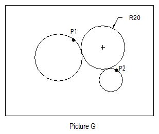
        Tangent-Tangent-Radius Mode : Method 3
        Illustrated below is an application on the use of Circle TTR mode
        to construct a circle tangent to another two circles. Study the
        prompt below to create these this types of circles.

        Example ( Picture G ) ;

            Command:  CIRCLE Specify center point for circle or
                               [3P/2P/Ttr (tan tan radius)] :                            TTR
            Specify point on object for first tangent of circle : pick 1       P1
            Specify point on object for second tangent of circle : pick 2  P2
            Specify radius of circle  : 20


To Be Continue.. Next > Drawing Arc.

Monday, May 2, 2011

Auto CAD - Save a Drawing

After you finish a drawing, you will have to save the  drawing files for later use. You can save the drawing at anytime using any of the save command. AutoCAD  provides automatic saving, backup files, and other options for saving.

To save a drawing from the file menu ;

Step 1 - From the File menu, choose save.


Step 2 - In the Save Drawing As dialog box under File Name, enter the new drawing name; the file extension is not required. Then choose Save. Picture below shows the Save Drawing As dialog box.

If you have previously have saved and named the drawing, AutoCAD saves any sequent changes and redisplays the command prompt. If you have never saved the drawing, the Save Drawing As dialog box is displayed.


To save a drawing automatically ;

Step 1 - From the Tools Menu, choose options.


Step 2 - After that choose OK.

In the Options dialog box, Open and Save tab, select Automatic Save and enter a number  in Minutes Between Saves. (Refer to Picture below).


START AUTOCAD DRAWING

When you open any AutoCAD software, an AutoCAD interface will show the startup dialog box.  The Startup dialog box is used to create or set up the first drawing file. There are many ways to set up a drawing file, they may start from scratch, a setup wizard or  a template file. You will use the same way to set up a next or new drawing file. Refer to picture below.


To begin a new drawing file, you must set up a drawing in the create new drawing dialog box. Refer to Picture 1.

HOW DO I SHOW A CREATE NEW DRAWING DIALOG BOX?


Using the Start from Scratch
One quick way you can use to set up your drawing is to start from scratch. You will create a new drawing based on the Imperial (English) or metric (Metric) measurement system.

•    English    -  The drawing limit is 12 x 9 inches.
•    Metric    -  The default drawing boundary is 429 x 297 millimeters.

Normally, when you choose this way the AutoCAD drawing file will show a default setting for a sheet of paper 12 units by 9 units and four– place decimal precision. Refer to picture below.


Using the Template
Click the button which is on the right side of the Start from Scratch button to display the “Use a Template” edit box. Picture below shows the “Use a Template” dialog box. This method is used to get a template file and design standard drawing sheet sizes.  Associated to each template file is a corresponding title block that is displayed in the Preview area. You may scroll through the various template files and get a glimpse of the title block tied to the template file.


Using the Setup Wizard
A setup wizard establishes the basic drawing setting step by step. You have two wizard options to help you set up a drawing (Refer to picture below).


Using the Quick Setup Wizard
In quick setup wizard dialog box you can set units of measurement, precision of displayed units and the grid limits or area. Picture below shows a dialog box with the units displayed.


In this dialog box there are five units of measurements available, namely Decimal, Engineering, Architectural, Fractional and Scientific. Normally for civil CADD subject you will use the decimal measurement. After that, click  Next > for setup area or paper size (Refer to Picture below).


In this dialog box you will put the value for Width and Length of the paper size area. When the setting of the drawing unit and area is completed, click the Finish button.

Using the Advanced Setup Wizard
You can set units of measurement, precision of displayed units and grid limits in the advanced setup dialog box. It also establishes the angle settings such as units of measurement style, precision, direction and orientation.

The first step is  you have to setup the unit in the advanced setup dialog box. In the advanced setup, to setup the unit you must set a precision for the unit that you have you chosen. The sample unit image will be previewed for your reference (Refer to Picture below).


After setting the unit, click Next > to setup the angle (Refer to Picture below). In this step you will setup the angle select the precision. There are five options of angle measurement which include the Decimal Degrees, Deg/Min/Sec, Grads, Radians and Surveyors. A sample of angle measurement will be displayed.


Than,   click  Next >   for  setup  angle   measure  (Refer to Picture below).  In  this  step the advanced setup dialog box will display how the angle is measured in the drawing. By default, angles are  measured  starting with  East for an angle  of 0.  Normally,  in  civil drawing we use North as a 0 angle.


The next step of the advanced setup dialog box deals with Angle Direction. All angles are by default measured in the counterclockwise direction. Use the dialog box illustrated in Picture below  to change from counterclockwise measurement of angles to clockwise angular measurements.


After changing the angle, click Next >. The last step of the advanced setup dialog box needs you to change the area of drawing . This method is similar to the quick setup dialog box. After that click Finish to display a setup drawing.